Photocatalytic Water Splitting
Energy and environmental issues at a global level are important topics. It is indispensable to construct clean energy systems in order to solve the issues. Hydrogen will play an important role in the system because it is an ultimate clean energy and it can be used in fuel cells. At present, hydrogen is mainly produced from fossil fuels such as natural gas by steam reforming. In this process, fossil fuels are consumed and CO2 is emitted. Hydrogen has to be produced from water using natural energies such as sunlight if one thinks of energy and environmental issues.

The Honda–Fujishima effect of water splitting using a TiO2 electrode was reported in the early 1970s. When TiO2 is irradiated with UV light, electrons and holes are generated as shown in Fig. 1. The photogenerated electrons reduce water to form H2 on a Pt counter electrode while holes oxidize water to form O2 on the TiO2 electrode with some external bias by a power supply or pH difference between a catholyte and an anolyte.
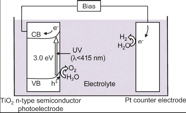
Fig. 1 The sketch map of Honda-Fujishima Effect.[1]
Bases of photocatalytic water splitting
The photon energy is converted to chemical energy accompanied with a largely positive change in the Gibbs free energy through water splitting. This reaction is similar to photosynthesis by green plants because these are uphill reactions. Therefore, photocatalytic water splitting is regarded as an artificial photosynthesis and is an attractive and challenging theme in chemistry.
![]()
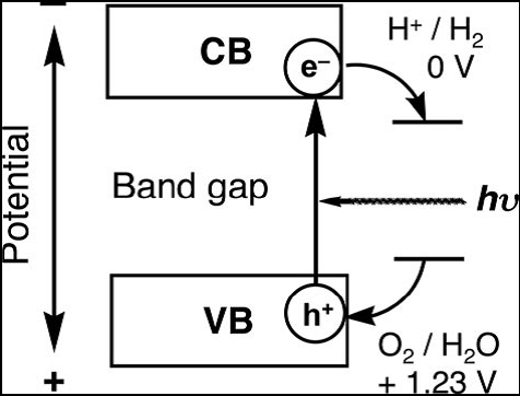
Photocatalytic reactions proceed on semiconductor materials as schematically shown in Fig. 2. Semiconductors have a band structure in which the conduction band is separated from the valence band by a band gap with a suitable width. When the energy of incident light is larger than that of a band gap, electrons and holes are generated in the conduction and valence bands, respectively. The photogenerated electrons and holes cause redox reactions similarly to electrolysis. Water molecules are reduced by the electrons to form H2 and are oxidized by the holes to form O2 for overall water splitting.
 |
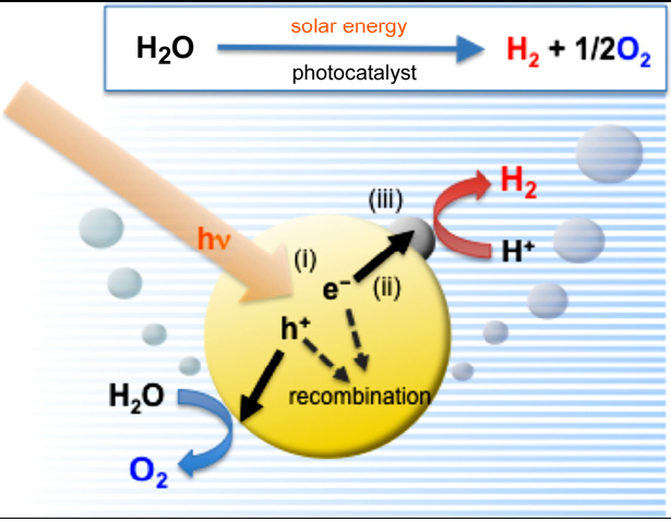 |
| Fig. 2 Principle of water splitting using semiconductor photocatalysts.[1] | Fig. 3 Main processes in photocatalytic water splitting [2] |
Photocatalysis on semiconductor particles involves three main steps as show in Fig. 3
(i) Absorption of photons with higher energies than the semiconductor bandgap, leading to the generation of electron–hole pairs in the semiconductor particles. Important points in the semiconductor photocatalyst materials are the width of the band gap and levels of the conduction and valence bands. The bottom level of the conduction band has to be more negative than the redox potential of H+/H2 (0 V vs. NHE), while the top level of the valence band be more positive than the redox potential of O2/H2O (1.23 V vs. NHE). Therefore, the theoretical minimum band gap for water splitting is 1.23 eV that corresponds to light of about 1100 nm: Band gap (eV) = 1240/λ (nm). Moreover, solar spectrum is mainly composed of visible light and infrared light but few ultraviolet light, so it is practical to develop visible-light-responsive photocatalysts rather than UV-light-responsive photocatalysts.
(ii) Charge separation and migration of photogenerated carriers. Crystal structure, crystallinity and particle size strongly affect the step. The higher the crystalline quality is, the smaller the amount of defects is. The defects operate as trapping and recombination centers between photogenerated electrons and holes, resulting in a decrease in the photocatalytic activity. If the particle size becomes small, the distance that photogenerated electrons and holes have to migrate to reaction sites on the surface becomes short and this results in a decrease in the recombination probability.
(iii) The surface chemical reactions. The important points for this step are surface character (active sites) and quantity (surface area). Even if the photogenerated electrons and holes possess thermodynamically sufficient potentials for water splitting, they will have to recombine with each other if the active sites for redox reactions do not exist on the surface. Co-catalysts such as Pt, NiO and RuO2 are usually loaded to introduce active sites for H2 evolution because the conduction band levels of many oxide photocatalysts are not high enough to reduce water to produce H2 without catalytic assistance.
Approaches to realize water splitting
There are two approaches to achieving water splitting: photocatalytic water splitting by powder semiconductors and photoelectrochemical water splitting by semiconductor electrodes.
photocatalytic water splitting is to split water into H2 and O2 using a single visible-light-responsive photocatalyst (a one-step system). Sacrificial reagents are often employed to evaluate the photocatalytic activity for water splitting, because overall water splitting is a tough reaction. When the photocatalytic reaction is carried out in an aqueous solution including a reducing reagent, in other words, electron donors or hole scavengers, such as alcohol and a sulfide ion, photogenerated holes irreversibly oxidize the reducing reagent instead of water. It enriches electrons in a photocatalyst and an H2 evolution reaction is enhanced. This reaction will be meaningful for realistic hydrogen production if biomass and abundant compounds in nature and industries are used as the reducing reagents. On the other hand, photogenerated electrons in the conduction band are consumed by oxidizing reagents (electron acceptors or electron scavengers) such as Ag+ and Fe3+ resulting in that an O2 evolution reaction is enhanced. These reactions using sacrificial reagents are studied to evaluate if a certain photocatalyst satisfies the thermodynamic and kinetic potentials for H2 or O2 evolution.
Because few stable semiconductors can absorb visible light and have a sufficiently high potential for water splitting, a two-step photoexcitation mechanism between two different photocatalysts (a two-step system) was developed. This process was inspired by natural photosynthesis in green plants and is known as the Z-scheme. In a two-step systems, the water splitting reaction is broken up into two stages: one for H2 evolution and the other for O2 evolution; these are combined by using a shuttle redox couple (Red/Ox) in the solution. Over a H2 evolution photocatalyst (referred to as a H2 photocatalyst), the photoexcited electrons reduce water to H2 and holes in the valence band oxidize the reductant (Red) to an oxidant (Ox). The oxidant is reduced back to the reductant by photoexcited electrons generated over an O2 evolution photocatalyst (referred to as an O2 photocatalyst), where the holes oxidize water to O2. This system lowers the energy required for photocatalysis, allowing visible light to be utilized more efficiently than in one-step systems. In other words, it enables a semiconductor to be used that has either a water reduction or oxidation potential on one side of the system.
![photocatalysis4 图4.粉体催化剂光分解水制氢示意图[1]](http://solar.iphy.ac.cn/wp-content/uploads/2011/12/photocatalysis.png) |
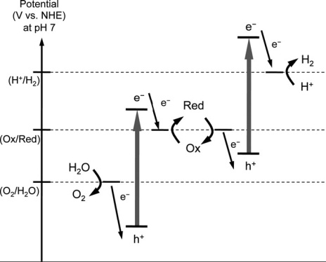 |
| Fig. 4 Photocatalytic water splitting by a powder photocatalyst[1] | Fig. 5 Schematic energy diagrams of photocatalytic water splitting two-step systems [2] |
Since the report of PEC water splitting using TiO2 electrodes under UV light, extensive efforts have been made to construct an efficient PEC water-splitting system and to develop new semiconductor materials for efficient photoelectrodes. Fig.

Fig. 6 Photoelectrochemical water splitting systems using n-type semiconductor photoanode (a), p-type semiconductor photocathode (b), and tandem system (c)
Experimental Setup
The most popular type of apparatus for water splliting is a gas-closed circulation system equipped with a vacuum line, a reaction cell and a gas sampling port that is directly connected to a gas chromatograph as shown in Fig. 7.
The apparatus should be air-free because the detection of O2 is very important for evaluation of photocatalytic water splitting. In general, efficient irradiation is conducted when an inner irradiation reaction cell is used. A high-pressure mercury lamp is often used with a quartz cell for photocatalysts with wide band gaps when intensive UV light with wavelength shorter than about 300nm is especially needed. When visible light irradiation is necessary a Xe-lamp with a cut-off filter is usually employed. It is important to know the spectrum of the incident light. It depends on a light source, a material of a reaction cell, an optical filter, a mirror, etc. A solar simulator that is a standard light source for evaluation of solar cells should ideally be used if solar hydrogen production is considered. A solar simulator with an air-mass 1.5 filter (AM-1.5) irradiates 100 mW/cm-2 of power. We have developed our Ⅲ-generation home-made apparatus for water splliting experiments with smart appearance, convenient operation process and excellent repeatability.
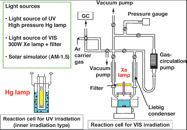
Fig. 7 An example of the experimental setup for photocatalytic water splitting. [1]
References:
1. Kudo, A. and Y. Miseki (2009). “Heterogeneous photocatalyst materials for water splitting.” Chemical Society Reviews 38(1): 253.
2. Abe, R. (2010). “Recent progress on photocatalytic and photoelectrochemical water splitting under visible light irradiation.” Journal of Photochemistry and Photobiology C: Photochemistry Reviews 11(4): 179-209.
News & Events
- A new world record 13.6% efficiency of CZTSSe solar cells by Institute of Physics, Chinese Academy of Sciences
- Congratulations for the graduation of Dr. Zhang and four undergraduate students
- Spring Hiking
- Na Zhou successfully defended her doctoral dissertation
- Our group joined the activity held by IOP labour union
